Tuesday, October 5, 2010

Computer-aided technologies

 
From Wikipedia, the free encyclopedia
Jump to: navigation, search
Illustration of the interaction of the various computer-aided technologies.
CAx tools in the context of product lifecycle management
Computer-aided technologies (CAx)[1] is a broad term describing the use of computer technology to aid in the design, analysis, and manufacture of products.
Advanced CAx tools merge many different aspects of the product lifecycle management (PLM), including design, analysis using finite element analysis (FEA), manufacturing, production planning, product testing using virtual lab models and visualization, product documentation, product support, etc. CAx encompasses a broad range of tools, both those commercially available and those which are proprietary to the engineering firm.
The term CAD/CAM (computer-aided design and computer-aided manufacturing) is also often used in the context of a software tool covering a number of engineering functions.

[edit] List of computer-aided technologies

A CAD model
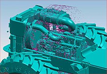
Simulation of airflow over an engine


Use Free Drawing Software to Work Like the Pros Without the Cost!

Free drawing software created a spark inside of me like nothing else had before by allowing me to bring what I was drawing on paper into the computer where I could instantly share it with the whole world over the internet.
There are a number of different types of drawing software out there. I checked out what I thought was the best free drawing software for each of the following areas: drawing and painting, illustration, and 3D. You may have heard of some commercial software, so I have compared these free packages to those commercial ones so you should have some idea of what to expect.


free drawing software #1 - SketchUP
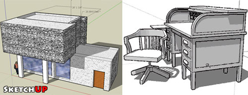
The fist software is called Sketchup and is brought to us for free by the kind people at Google. This free drawing software is a little different than the other packages. This one deals in the third dimension, or 3D. I first saw this program a few years ago, and it looks like Google has bought it and now released it for free - lucky us! I gave it a try and in about 10 minutes from installing the program I had created this little art-modern living space. I think this software is really cool - and if you are studying perspective, or are interested in architectural or technical drawings I would really highly recommend it. I'm having so much fun with this I think I may try designing a dream house for myself! If 3d and perspective sounds interesting to you go check it out at http://sketchup.google.com.

Thursday, September 30, 2010

This standard establishes uniform drafting practices for preparation of engineering drawing

1    SCOPE:
This standard establishes uniform drafting practices for preparation of engineering drawings.
2    APPLICATION: 
This standard applies to all new Sauer-Danfoss (SD) Engineering drawings.
3    GENERAL:
To ensure that drawings are unambiguous, international standards (ISO and IEC) are used for general principles of presentation, definitions, scales, dimensioning, symbols, tolerances, thread designations etc.
If no international standards are available, European standards (EN), national standards or Sauer-Danfoss Standards and Guidelines are used.
The reference to GS-0074 is as shown in figure 1.
If there is a reference to GS-0074, one or more of the Sauer-Danfoss documents listed in this Guideline are used.
If other standards are used, they must be the subject of special reference.
If a drawing refers to a standard that conflicts with a standard in the body of GS-0074, then the standard noted on the drawing shall have priority.
The English language version is the original and the reference in case of dispute.

Saturday, September 25, 2010

activity design

system and service enriching our life standard represent result of activity design of all technician. Basically this activity design differentiate the technique with the science and research ; technique expert is  a desain , creator or constructor
 Process the design represent the charm effort and challange, and technician desain very reliing on  of graph as a way of to create, to noting, analysing, and communicating with others, about concept or idea design. Ability to communicate graphically represent the elementary matter in this case
 team Design make a move in five step in course of desain. To become  a success team desain, each;every team member shall comprehend this process and know how to to fulfill their role each
 the step desain is
1. Identifying problem and [cutomer/ client]
2. concept and idea
3. compromise to decision
4. model and prototype
5. draw the [job/activity]
 ideally is making plan to walk to listen go the the phase, but if got by a new information, may be necessary return and repeat procedure.

Monday, September 20, 2010

HOW USE THE ISO CATALOGUE

How to use the ISO Catalogue

The online ISO Standards listing integrates both the ISO Catalogue of published standards and the ISO Technical programme of standards under development. From within the listing, the user can choose to display, as required, Published standards and/or Standards under development and/or Withdrawn standards and/or Projects deleted.
By default, the ISO Standards listing presents the complete listing of Published standards AND Standards under development. The user chooses whether to access the listing By ICS (classified by subject in accordance with the International Classification for Standards) or By TC (sorted according to the ISO technical committee responsible for the preparation and/or maintenance of the standards).

International Standards and other deliverables

The terms International Standards and ISO standards used in these listings denote all standards-type documents, including guides, international standardized profiles, recommendations, technical reports, technical trends assessments, etc. The document type is indicated in its reference number. The following bibliographic information is given for each document:
Reference number - consists of a prefix, a serial number and the year of publication. The prefix will usually be "ISO" to indicate that the publication is an ISO International Standard.
The prefix ISO/IEC denotes a joint ISO and IEC (International Electrotechnical Commission) publication. ISO/IEC International Standards are most often developed by Joint ISO/IEC Technical Committee JTC 1. IEC International Standards with the prefix IEC, but which carry both the ISO and IEC logos, are also  included in the catalogue. Such standards either belong to JTC 1, or have been developed in close cooperation with an ISO committee.
The following prefixes similarly denote joint international standards:
ISO/ASTM joint ISO and ASTM (American Society of Testing and Materials) International Standard
ISO/CIE: joint ISO and CIE (International Commission on Illumination) International Standard
ISO/HL7 joint ISO and HL7 (Health Level Seven) International Standard
ISO/IEEE: joint ISO and IEEE (Institute of Electrical and Electronics Engineers) International Standard
ISO/OECD joint ISO and OECD (Organisation for Economic Cooperation and Development) International Standard
The prefix may also contain an indication of the type of document:
Amd. denotes an Amendment - a normative document, developed according to consensus procedures, approved according to the procedures relevant to the document being amended, and which changes the technical normative elements of that document.
Cor. denotes a Technical corrigendum - a document issued to correct a technical error or ambiguity in a normative document or to correct information that has become outdated, provided the modification has no effect on the technical normative elements of the document it corrects.
Guide - redefined as an informative document only. Previously ISO and ISO/IEC Guides were developed as either a document dealing with non-normative matters relating to international standardization or a normative document developed by a structure other than a TC/SC, e.g. a policy development committee. A number of such guides are still valid.
ISP denotes an International Standardized Profile - an internally agreed, harmonized document which identifies a standard or group of standards, together with options and parameters, necessary to perform a function or set of functions.
IWA denotes an International Workshop Agreement
PAS denotes a Publicly Available Specification
R denotes a Recommendation. This designation was used up to 1972, when ISO began to publish International Standards. Since then, as they have been revised, ISO recommendations have gradually been republished as International Standards. A very limited number of ISO recommendations still remain valid and available.
TR denotes a Technical Report
TS denotes a Technical Specification
TTA denotes a Technology Trends Assessment - a document published to respond to the need for global collaboration on standardization questions during the early stages of technical innovation and which gives the state of the art or trend in emerging fields. TTAs are typically the result of prestandardization work or research
The prefix is followed by a serial number which may include a part number, separated by a hyphen from the main number. The serial number of a published standard is followed by the year of publication separated from the serial number by a colon.
Title of the standard including, if relevant, the number and title of a specific part of the standard
Current stage - to allow the monitoring of a standard's development and life cycle in a systematic way, a four-digit stage code is used, which indicates the standard's current status. The current stage code is given for each standard or project. The code is linked to a stage code chart giving the explanation for each stage code.
TC/SC - Technical committee/subcommittee - refers to the ISO technical committee and subcommittee responsible for the development and maintenance of the standard. Certain documents are developed and maintained by other ISO organs or by other international organizations. A link leads to information about the committee or organization concerned.
Language - the official languages of ISO are English, French and Russian. ISO International Standards and standards-type documents published by the Central Secretariat are usually in separate (monolingual) English (en) and French (fr) editions and, less frequently, in Russian (ru). Some standards, especially those containing terminology, are published as a bilingual (any two of the official languages), or trilingual (English/French/Russian) edition.  The ISO Central Secretariat also publishes certain official translations in non-official languages. To date, these include standards in Spanish (es) and Arabic (ar).
NOTE: It is possible for standards - and notably terminologies and vocabularies - to include some content in non-official languages. Where applicable, information on the non-official language content is usually given in the standard's abstract in the bibliographical data.
A number of International Standards developed by ISO technical committees require, with a view to their updating or implementation, a competent body which has the requisite infrastructure for ensuring they are used effectively. Information on these bodies, designated by ISO to serve as maintenance agencies or registration authorities, is accessed through the link Maintenance agencies and registration authorities.

Tuesday, September 14, 2010

computer-aided drafting and design (CADD)

Computer-aided design (CAD), also known as computer-aided drafting and design (CADD), is the use of computer technology for the process of design and design-documentation. Computer Aided Design describes the way in which technology is folded into a design process. Computer Aided Drafting describes the process of drafting with a computer. CADD software, or environments, provide the user with input-tools for the purpose of streamlining design processes; drafting, documentation, and manufacturing processes. CADD output is often in the form of electronic files for print or machining operations. The development of CADD-based software is in direct correlation with the processes it seeks to economize; industry-based software (construction, manufacturing, etc.) typically uses vector-based (linear) environments whereas graphic-based software utilizes raster-based (pixelated) environments.
CADD environments often involve more than just shapes. As in the manual drafting of technical and engineering drawings, the output of CAD must convey information, such as materials, processes, dimensions, and tolerances, according to application-specific conventions.
CAD may be used to design curves and figures in two-dimensional (2D) space; or curves, surfaces, and solids in three-dimensional (3D) objects.[1]
CAD is an important industrial art extensively used in many applications, including automotive, shipbuilding, and aerospace industries, industrial and architectural design, prosthetics, and many more. CAD is also widely used to produce computer animation for special effects in movies, advertising and technical manuals. The modern ubiquity and power of computers means that even perfume bottles and shampoo dispensers are designed using techniques unheard of by engineers of the 1960s. Because of its enormous economic importance, CAD has been a major driving force for research in computational geometry, computer graphics (both hardware and software), and discrete differential geometry.[2]
The design of geometric models for object shapes, in particular, is often called computer-aided geometric design (CAGD).

Overview

Current computer-aided design software packages range from 2D vector-based drafting systems to 3D solid and surface modellers. Modern CAD packages can also frequently allow rotations in three dimensions, allowing viewing of a designed object from any desired angle, even from the inside looking out. Some CAD software is capable of dynamic mathematic modeling, in which case it may be marketed as CADDcomputer-aided design and drafting.
CAD is used in the design of tools and machinery and in the drafting and design of all types of buildings, from small residential types (houses) to the largest commercial and industrial structures (hospitals and factories).
CAD is mainly used for detailed engineering of 3D models and/or 2D drawings of physical components, but it is also used throughout the engineering process from conceptual design and layout of products, through strength and dynamic analysis of assemblies to definition of manufacturing methods of components. It can also be used to design objects.
CAD has become an especially important technology within the scope of computer-aided technologies, with benefits such as lower product development costs and a greatly shortened design cycle. CAD enables designers to lay out and develop work on screen, print it out and save it for future editing, saving time on their drawings.
Occupations that use CAD include designers, architects, and developers.

[edit] Uses

Computer-aided design is one of the many tools used by engineers and designers and is used in many ways depending on the profession of the user and the type of software in question.
CAD is one part of the whole Digital Product Development (DPD) activity within the Product Lifecycle Management (PLM) process, and as such is used together with other tools, which are either integrated modules or stand-alone products, such as:
CAD is also used for the accurate creation of photo simulations that are often required in the preparation of Environmental Impact Reports, in which computer-aided designs of intended buildings are superimposed into photographs of existing environments to represent what that locale will be like were the proposed facilities allowed to be built. Potential blockage of view corridors and shadow studies are also frequently analyzed through the use of CAD.

[edit] Types

There are several different types of CAD. Each of these different types of CAD systems require the operator to think differently about how he or she will use them and he or she must design their virtual components in a different manner for each.
There are many producers of the lower-end 2D systems, including a number of free and open source programs. These provide an approach to the drawing process without all the fuss over scale and placement on the drawing sheet that accompanied hand drafting, since these can be adjusted as required during the creation of the final draft.
3D wireframe is basically an extension of 2D drafting. Each line has to be manually inserted into the drawing. The final product has no mass properties associated with it and cannot have features directly added to it, such as holes. The operator approaches these in a similar fashion to the 2D systems, although many 3D systems allow using the wireframe model to make the final engineering drawing views.
3D "dumb" solids (programs incorporating this technology include AutoCAD) are created in a way analogous to manipulations of real world objects. Basic three-dimensional geometric forms (prisms, cylinders, spheres, and so on) have solid volumes added or subtracted from them, as if assembling or cutting real-world objects. Two-dimensional projected views can easily be generated from the models. Basic 3D solids don't usually include tools to easily allow motion of components, set limits to their motion, or identify interference between components.
3D parametric solid modeling require the operator to use what is referred to as "design intent". The objects and features created are adjustable. Any future modifications will be simple, difficult, or nearly impossible, depending on how the original part was created. One must think of this as being a "perfect world" representation of the component. If a feature was intended to be located from the center of the part, the operator needs to locate it from the center of the model, not, perhaps, from a more convenient edge or an arbitrary point, as he could when using "dumb" solids. Parametric solids require the operator to consider the consequences of his actions carefully.
Some software packages provide the ability to edit parametric and non-parametric geometry without the need to understand or undo the design intent history of the geometry by use of direct modeling functionality. This ability may also include the additional ability to infer the correct relationships between selected geometry (e.g., tangency, concentricity) which makes the editing process less time and labor intensive while still freeing the engineer from the burden of understanding the model’s design intent history. These kind of non history based systems are called Explicit Modellers or Direct CAD Modelers. The first Explicit Modeling system was introduced to the world at the end of 80's by Hewlett-Packard under the name SolidDesigner.
Draft views are able to be generated easily from the models. Assemblies usually incorporate tools to represent the motions of components, set their limits, and identify interference. The tool kits available for these systems are ever increasing; including 3D piping and injection mold designing packages.
Mid range software are integrating parametric solids more easily to the end user: integrating more intuitive functions (SketchUp), using the best of both 3D dumb solids and parametric characteristics (VectorWorks), making very real-view scenes in relative few steps (Cinema4D) or offering all-in-one (form•Z).
Top end systems offer the capabilities to incorporate more organic, aesthetics and ergonomic features into designs (Catia, GenerativeComponents). Freeform surface modelling is often combined with solids to allow the designer to create products that fit the human form and visual requirements as well as they interface with the machine.

[edit] Technology

A CAD model of a mouse.
Originally software for Computer-Aided Design systems was developed with computer languages such as Fortran, but with the advancement of object-oriented programming methods this has radically changed. Typical modern parametric feature based modeler and freeform surface systems are built around a number of key C modules with their own APIs. A CAD system can be seen as built up from the interaction of a graphical user interface (GUI) with NURBS geometry and/or boundary representation (B-rep) data via a geometric modeling kernel. A geometry constraint engine may also be employed to manage the associative relationships between geometry, such as wireframe geometry in a sketch or components in an assembly.
Unexpected capabilities of these associative relationships have led to a new form of prototyping called digital prototyping. In contrast to physical prototypes, which entail manufacturing time and in the design.
Today, CAD systems exist for all the major platforms (Windows, Linux, UNIX and Mac OS X); some packages even support multiple platforms.
Right now, no special hardware is required for most CAD software. However, some CAD systems can do graphically and computationally expensive tasks, so good graphics card, high speed (and possibly multiple) CPUs and large amounts of RAM are recommended.
The human-machine interface is generally via a computer mouse but can also be via a pen and digitizing graphics tablet. Manipulation of the view of the model on the screen is also sometimes done with the use of a spacemouse/SpaceBall. Some systems also support stereoscopic glasses for viewing the 3D model.


Monday, September 13, 2010

Basic conventions and applications for leader lines and reference lines

Basic conventions and applications for leader lines and reference lines
1 Scope
This part of ISO 128 specifies general rules on the presentation of leader and reference lines and their components as
well as on the arrangement of instructions on or at leader lines in all kinds of technical documents.
2 Normative reference
The following normative document contains provisions which, through reference in this text, constitute provisions of
this part of ISO 128. For dated references, subsequent amendments to, or revisions of, any of these publications do
not apply. However, parties to agreements based on this part of ISO 128 are encouraged to investigate the
possibility of applying the most recent edition of the normative document indicated below. For undated references,
the latest edition of the normative document referred to applies. Members of ISO and IEC maintain registers of
currently valid International Standards.
ISO 128-20:1996, Technical drawings — General principles of presentation — Part 20: Basic conventions for lines.
3 Terms and definitions
For the purposes of this part of ISO 128, the following terms and definitions apply.
3.1
leader line
continuous narrow line which establishes the connection between the features of a graphical representation and
additional alphanumeric and/or written instructions (notes, technical requirements, item references, etc.) in an
unambiguous manner
3.2
reference line
continuous narrow line connecting with the leader line horizontally or vertically and on or at which the additional
instructions are indicated
4 Presentation of leader lines
Leader lines are executed as continuous narrow lines in accordance with ISO 128-20. They are drawn preferably at an
angle to the relevant representation and/or the frame limiting the drawing sheet, and not parallel to adjacent lines, e.g.
hatching lines. The inclination to the relevant lines shall be . 15°. See Figures 1 to 13.
Leader lines may be drawn with sharp kinks (see Figure 5), and two or more leader lines may be joined up (see
Figures 2, 5, 7, 8 and 11). They should not cross other leader lines, reference lines or indications, such as graphical
symbols or dimensional values.
1
This is a free 5 page sample. Access the full version online.